RONDO
the spinner that computes
A circular slide rule riding on a print-in-place roller bearing. It multiplies and divides by turning, and it prints in one piece with no supports and nothing to assemble.
The bearing is not designed. It is copied.
The interesting part of RONDO is the part nobody chose. Its roller bearing was not modelled from a datasheet or eyeballed until it looked right — every roller and race dimension was measured out of the gcode of a 608 bearing that was actually printed on the A1 Mini, pulled back off the printer's own microSD card and read toolpath by toolpath.
That matters because a print-in-place bearing lives or dies on one number: the clearance between parts that must come out of the printer already moving. Guess it and you get either a fused lump or a rattling mess. Copy it from a part that demonstrably worked and you inherit a fit the printer has already proven it can hold.
And the clearance is a normal offset, not a radial one. On the waist and flanges those are the same thing, so a radial copy looks correct there. But on the 45° flanks a radial offset would have quietly tightened the gap by a factor of √2 and seized the bearing. The races are built by offsetting along the roller's own normal, and the result is checked against the measured walls layer by layer.
What the printed one got wrong
Four faults came back from the test fit. Two of them were not what the symptom suggested, and the first one was a claim this page used to make.
1. The rollers fell out — and “the profile is the retention” was wrong
This page previously said that a roller could not escape upward because its flanges sat trapped under the race lips. There were no lips. The roller was exactly as tall as the discs and its flange, at Ø4.496 mm, was narrower than the 4.796 mm mouth the channel presented at each face. The spool was held by a wedge, not a lock, and a wedge yields to whatever elastic give the plastic has.
The measurement is worth stating precisely, because it says the rollers were not the loose part at all. Forcing a single roller out of a race that stays flat takes 0.75 mm of material interference — it cannot happen. But lifting the whole rotor out of the base, which spills every roller at once, peaks at only 0.25 mm, and past 4.5 mm of lift there is no resistance left whatsoever. 0.25 mm across a 42 mm PLA disc is nothing. The rollers were not escaping. They were being tipped out.
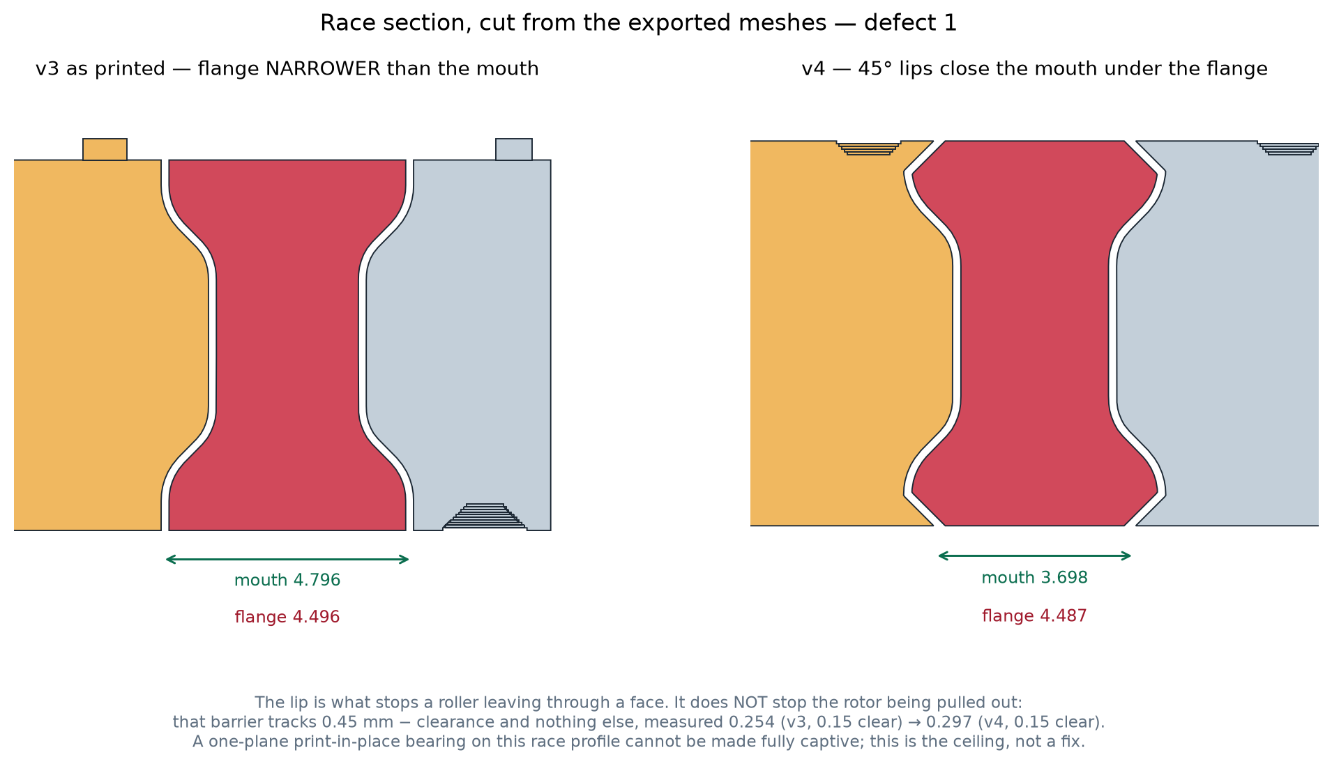
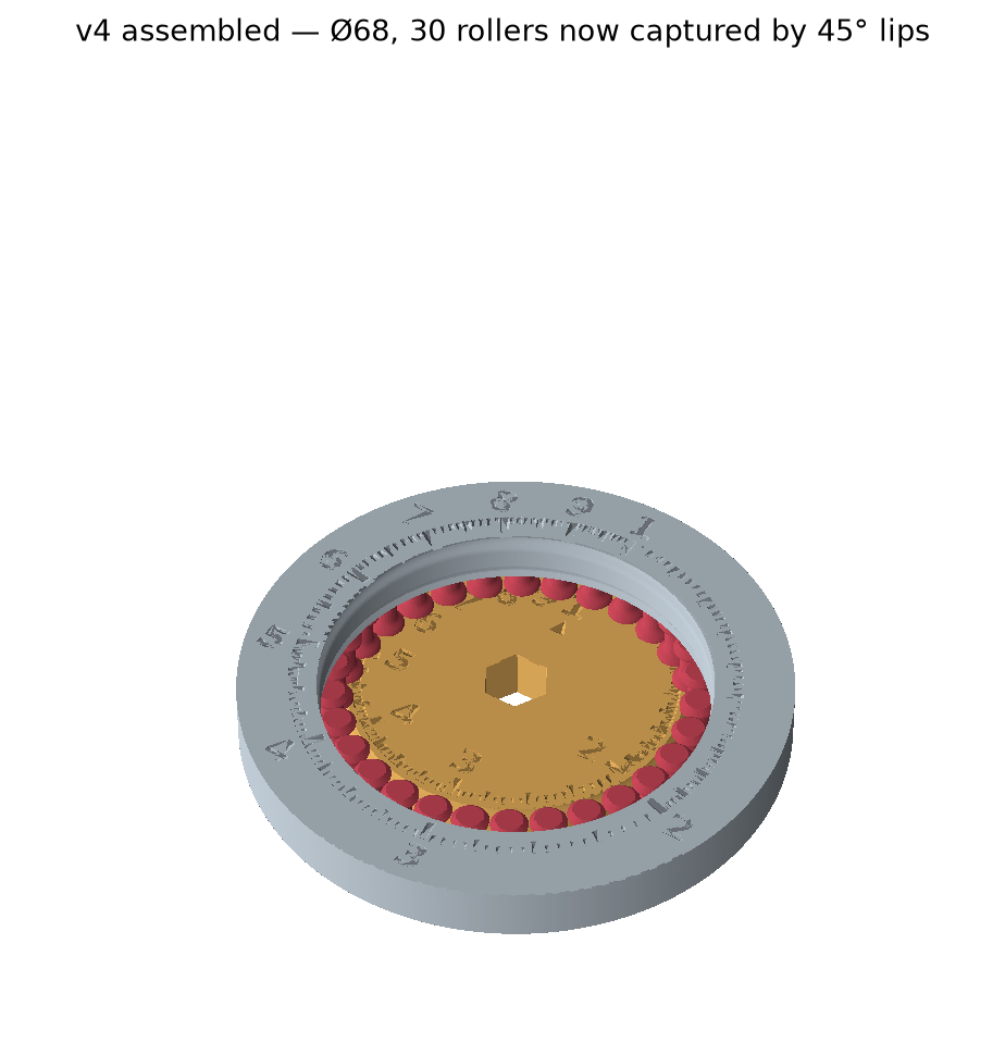
So v4 chamfers the roller's end edges at 45° and gives both races the matching lip. The mouth now closes to 3.696 mm — below the flange diameter — so 0.40 mm of flange sits under the lip on each side and a roller cannot pass through a face at any clearance. The chamfer is what lets the roller keep printing flat on the bed; raising it to make room for a lip would have started its first layer in mid-air.
And the part where the obvious fix did nothing
The lip does not stop the rotor being pulled out. That is worth dwelling on, because the first cut of v4 assumed it would and shipped a number that had not moved at all.
Sweeping the chamfer from 0.55 mm to 1.15 mm — more than doubling how much flange sits captured — moved the pull-apart barrier from 0.250 mm to 0.267 mm. Nothing. The cheapest escape never goes through a face: the roller rides up with the rotor and squeezes sideways into the rotor's own race groove, which by design has 0.90 mm of room in it. What that costs is whatever radial interference is left once the running clearance has been spent, and the measurement is almost perfectly linear:
| running clearance | force needed to pull the rotor out |
|---|---|
| 0.20 mm | 0.250 mm of interference |
| 0.18 mm | 0.270 mm |
| 0.15 mm | 0.297 mm |
barrier ≈ 0.45 mm − clearance. The clearance is the only lever
there is. Which caught a mistake in the making: v4's first draft had opened the
clearance to 0.20 mm for PETG in the same edit that added the lip —
capture up, dodge up, net zero. It is now back at the proven 0.15 mm, and the
looser set ships as a separate spare rather than as the default.
Stated plainly, because a limit is more useful than a claim: a one-plane print-in-place bearing on this race profile cannot be made axially captive. Nothing that fits inside 7.04 mm of height will do it. v4 stops rollers leaving through a face and buys about 20% on the pull-apart force. Beyond that needs a taller bearing or a second interlock plane, and that is a different object.
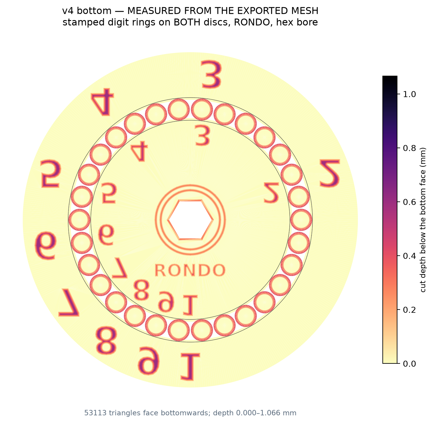
2. The stamped numbers were legible — until they were cut in half
The underside digits came back unreadable, and the obvious diagnosis — strokes too thin — was wrong. The glyphs were plenty fat. They were chopped and merged: seven of the nine digits ran past the edge mask and were sliced flat (the 7 lost 4.9% of its area), and the 7 and the 8 closed to a 0.53 mm gap, narrower than two extrusions, so they printed as one blob.
v4 solves the ring radius and the character size against both constraints at once and refuses to build if either is violated, so a layout that clips or collides is now a build failure rather than something discovered after a print. The outer disc got the digit ring it never had, too — it was dropped from v3 only because the half-size dial had no room for one.
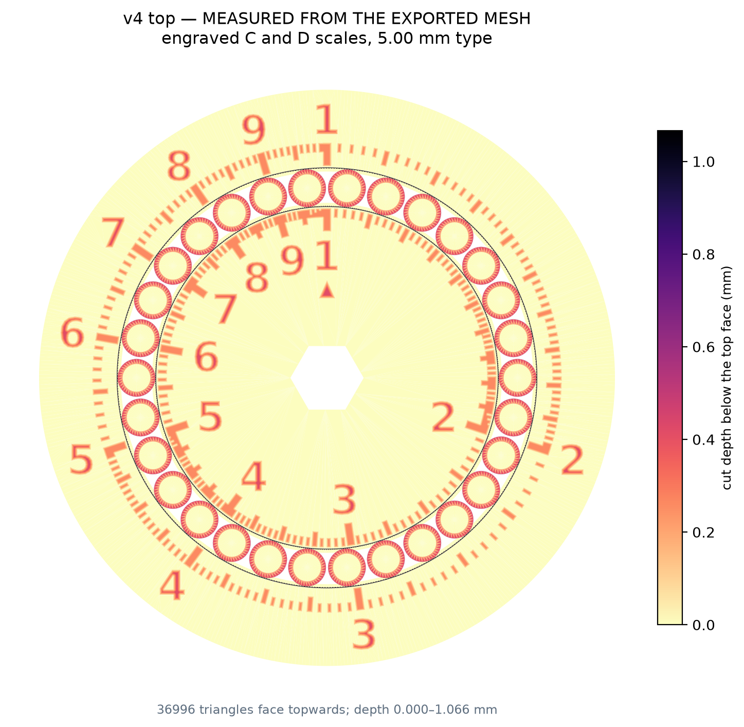
3. The top faces had no numbers, because they were never printable
The numerals were in the v3 file, standing 0.40 mm proud. They could not print. At 1.80 mm and 2.10 mm tall, the thinnest stroke in the typeface measures 0.321 mm and 0.374 mm — both below the 0.42 mm width of a single extrusion. The slicer had nothing to lay down.
| scale | type size | thinnest stroke | vs one extrusion |
|---|---|---|---|
| v3 outer | 1.80 mm | 0.321 mm | under |
| v3 inner | 2.10 mm | 0.374 mm | under |
| v4 both | 5.00 mm | 1.121 mm | 2.7× |
v4 sizes the type off the nozzle rather than off the dial, and cuts the scales into the face instead of raising them — an engraved pocket has no fragile ribs and no support problem. Forcing 5 mm type onto the outer ring is what pushed the whole part from Ø55 to Ø68; on Ø55 a legible outer scale and a small part were mutually exclusive.
Why these pictures are made the hard way
None of the figures on this page is a drawing of what the generator meant to cut. Each one loads the finished mesh and colours its triangles by how deep they sit below the face they belong to.
That distinction earned itself. An earlier v3 export came out with a completely blank underside — no digits, no name, no texture — and every check still reported success. The geometry was computed correctly as flat outlines; the boolean that should have cut those outlines into the solid silently did nothing and returned no error. Both the verification script and the preview image were reading the same flat outlines, so both cheerfully showed a fully stamped disc that did not exist in the file anyone would have printed.
Two confirmations that share a source are one confirmation. The fix was to measure the mesh itself, and to make the build fail loudly when a cut removes no material — the blank version and the correct one differ by 0.04 cm³, the only number that would ever have given it away. The same habit caught two more things in v4 that no render would have shown: a retention lip that came out at 36.6° instead of 45° and would have printed as an unsupported overhang, and four non-manifold edges out of 313,907 where the wordmark landed exactly tangent to a texture ring.
One governing constraint decides every stamped feature on the part, and it is worth stating because it is not obvious: for a cut with 45° walls, the deepest it can go is half the width of the stroke. Erode the letter inward as you rise and it closes to a point. Legibility and depth are the same question — thin numerals cannot be stamped deep, no matter how much you want them to be.
Related
The earlier nested-ring version of this idea, which computes the same way without a bearing, is at The Nested Spinner. More prints at 3D Printed Projects.